- VMware Technology Network
- :
- Networking
- :
- VMware NSX
- :
- VMware NSX Discussions
- :
- TOR design question
- Subscribe to RSS Feed
- Mark Topic as New
- Mark Topic as Read
- Float this Topic for Current User
- Bookmark
- Subscribe
- Mute
- Printer Friendly Page
- Mark as New
- Bookmark
- Subscribe
- Mute
- Subscribe to RSS Feed
- Permalink
- Report Inappropriate Content
TOR design question
I am a bit confused and need clarifying on the idea of spine/leaf and TOR switch connectivity. I will ask the question a couple different ways.
For simplicity sake, lets say i have 2 TOR switches in a rack (for redundancy) and 2 spines.
Does each TOR switch run back to each spine or do you create a port channel or stack the 2 TOR switches to essentially make one leaf out of the 2 switches and then run 1 line back to each spines so that the spine sees it as one entity. Ultimately you would need to run 2 lines back to the spine for redundancy but do you employ communication between the 2 leafs in anyway through a port channel or stacking considering they are supplying the same service to the rack?
I know they say that you dont connect leafs to other leafs but in the case of redundancy in TOR switches, you would have to correct?
Most diagrams i have seen show 1 TOR Leaf going up each spine. What does it look like if you have 2 TOR switches for redundancy. Do they talk to each other or do they get wired seperately back to each spine?
Hopefuly this makes sense. I am not sure how to ask it.
- Mark as New
- Bookmark
- Subscribe
- Mute
- Subscribe to RSS Feed
- Permalink
- Report Inappropriate Content
In an L3 leaf/spine topology, leaf switches connect only to spines and each leaf is connected to each spine, so in your example with 2 leaf switches and 2 spines, you'd have at least 2 uplinks from each leaf switch (one or more each to each spine) and no direct link between the 2 leaf switches. The redundancy is achieved by utilizing L3 ECMP links between leaf/spine switches and your NSX hosts will have 2 uplinks (1 to each leaf) that you can either have in an active/standby (aka "failover" for NIC teaming setting) or load balance active/active based on source port ID or IP/MAC hash.
- Mark as New
- Bookmark
- Subscribe
- Mute
- Subscribe to RSS Feed
- Permalink
- Report Inappropriate Content
So simply put......in the example they are not considered 1 leaf.....they are considered 2 leafs.
Therefore they need to each be plumbed back to each spine (in this case 2). I would have 2 connections coming out of each TOR to each spine (2 spines).
Redundancy is done via ECMP and the fact that each host would have 2 (or more NICs) which would be setup to connect to each TOR switch.
I think that makes sense.
It is simple when you have 1 TOR and 1 spine but that isnt redundant.
Most diagrams you see will show 2 switchs in a top of rack but only one link going back to the spine. I am sure this is for simplicity sake but it is confusing.
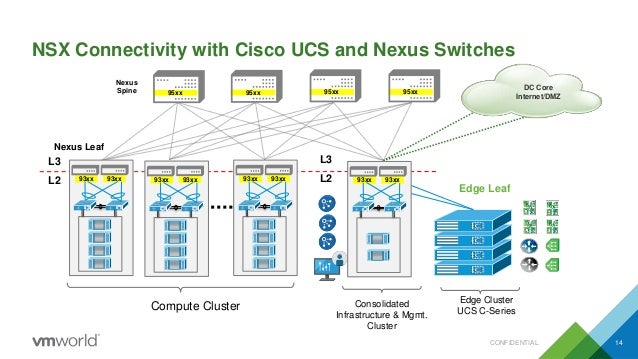
Show here for example....look at the 93XX:
You can see they only have 1 connection per to the spines despite having 2 93xx switches in the rack for redundancy. Perhaps this was for simplicity sake. It is a UCS diagram but i dont image that being any different. Perhaps it is?
- Mark as New
- Bookmark
- Subscribe
- Mute
- Subscribe to RSS Feed
- Permalink
- Report Inappropriate Content
Yes, you've still got 2 leaf switches in that scenario. That particular diagram just adds an extra layer as it's Cisco UCS specific so you've also got fabric interconnects in between the chassis and leaf switches as well as VPC links for additional throughput due to the traffic aggregation happening there. I agree that this diagram is misleading in that it only shows one link to each spine per rack where you'd actually want one per leaf switch so I assume that the author just took some liberties to keep things a little less cluttered.
- Mark as New
- Bookmark
- Subscribe
- Mute
- Subscribe to RSS Feed
- Permalink
- Report Inappropriate Content
Thank you for clearing that up.
The VPC links are confusing there as well considering leafs should never connect to other leafs. (from what i understand). That is what started this whole mess for me was seeing this and thinking......hey....perhaps when you have 2 switches for redundancy maybe you set them up so they appear as one device and then only plumb 1 line back to the spine per rack. I guess that isnt redundant though so that makes 0 sense. That link goes down and you lose both switches. Heck....you could have 10 switches and they would all be dead at that point. My end goal is to setup a UCS system properly.
Thanks again for the clear explanation.
- Mark as New
- Bookmark
- Subscribe
- Mute
- Subscribe to RSS Feed
- Permalink
- Report Inappropriate Content
The leaf-spine fabric is normally created based on layer-3 fabric.
But you can also create layer-2 fabric, depends on the vendor and the design.
Here's a sample of layer-3 fabric

The first compute leaf has 2 leaf switches configured in MLAG (vPC in Cisco).
The other leaf switches are only one I guess this is for simplicity.
Each leaf switch will have L3 point to point links to each Spine switches
Here's the sample using layer-2 fabric.
In layer-2 fabric, leaf to spine links are using MLAG/vPC

Author of VMware NSX Cookbook http://bit.ly/NSXCookbook
https://github.com/bayupw/PowerNSX-Scripts
https://nz.linkedin.com/in/bayupw | twitter @bayupw