- VMware Technology Network
- :
- Cloud & SDDC
- :
- ESXi
- :
- ESXi Discussions
- :
- Re: Setting up routing between vlans on Virtual Sw...
- Subscribe to RSS Feed
- Mark Topic as New
- Mark Topic as Read
- Float this Topic for Current User
- Bookmark
- Subscribe
- Mute
- Printer Friendly Page
- Mark as New
- Bookmark
- Subscribe
- Mute
- Subscribe to RSS Feed
- Permalink
- Report Inappropriate Content
Setting up routing between vlans on Virtual Switch
I am using VMware in a development environment. Part for the development process requires a simulation of a geo-redundant cluster setup for the VMs. As part of each setup, the cluster uses its own Virtual Private Network 192.168.x.x/24 network
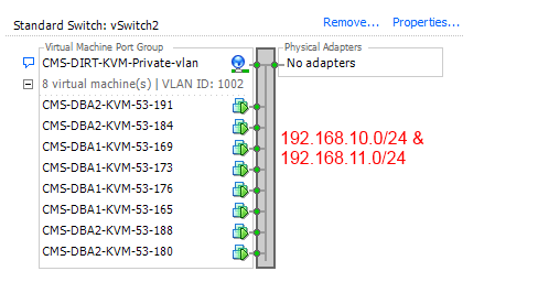
Right now I have both clusters in the same vlan on the virtual switch. With this setup I am able to access both subnets 192.168.10.0/24 and 192.168.11.0/24 both clusters can talk to each other. (i.e. I can reach and 192.168.11.0/24 system in the cluster from any 192.168.10.0/24 ip, and vice versa.) See Attached: VMware_Single_vlan_setup.png
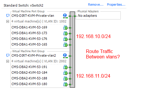
Now I am trying to place each cluster in its own vlan. The problem that I am seeing is that because 192.168.10.0/24 and 192.168.11.0/24 are on two different vlans, I have lost the ability to access each the other network (i.e. I can NOT reach and 192.168.11.0/24 system in the cluster from any 192.168.10.0/24 ip, and vice versa.) See Attached: VMware_Multi_vlan_setup.png
I think I need to setup a route from vlan 1001 to 1002 on the virtual switch, I have looked at Understand How Virtual Machine Traffic Routes https://communities.vmware.com/docs/DOC-25426 and some other docs, but I cannot seem to find any documentation on this specific setup.
Has anyone done this in the past. How can i forward the IP traffic from each subnet to each other?
Thanks
- Mark as New
- Bookmark
- Subscribe
- Mute
- Subscribe to RSS Feed
- Permalink
- Report Inappropriate Content
The purpose of VLANs is to separate network traffic, so what you may want to do is to setup a virtual machine which acts as the router (e.g. pfSense).
In case you ever want to attach that vSwitch to a physical switch, remember that some switches reserve VLAN 1002 trough 1005.
André
- Mark as New
- Bookmark
- Subscribe
- Mute
- Subscribe to RSS Feed
- Permalink
- Report Inappropriate Content
If you have a L3 or "light" L3 switching you can trunk your uplinks and switch ports and create the VLANs on the switch, IP the VLANs and use inter VLAN routing.
(I can make an example of this in Packet Tracer as well if you like.)
--------
Another option (depending on your network architecture) is to configure your gateway for both VLANs ala router on a stick.
I am going to do an example here for ya in Packet Tracer.
Router
Gi0/1 192.168.1.1
Gi0/1.1 192.168.50.1 VLAN 50
Gi0/1.2 192.168.51.1 VLAN 51
Switch will represent quasi host/switch.
The uplink is simply set to trunk all. In production set to trunk only required VLANs.
On the switch your PG's will be represented by individual ports.
Fa0/1 is VLAN 50
Fa02 is VLAN 51
Now each server in the private VLAN / PG's will be shown as PC's.
PC 1 is 192.168.50.2
PC 2 is 192.168.51.2
See screen shot. Both PC's (servers) can ping each other in the separate VLAN's and simulated port groups.

Also including Packet Tracer File.
- Mark as New
- Bookmark
- Subscribe
- Mute
- Subscribe to RSS Feed
- Permalink
- Report Inappropriate Content
Hi,
Bring in the switch to make there 2 subnet to ping each other and let us know on what are the components u r using to do so.
Regards
Raj
- Mark as New
- Bookmark
- Subscribe
- Mute
- Subscribe to RSS Feed
- Permalink
- Report Inappropriate Content
Confused, surely you can't route between those subnets without a L3 device?
subnet 192.168.10.0 /24 and 192.168.11.0 /24 ?
- Mark as New
- Bookmark
- Subscribe
- Mute
- Subscribe to RSS Feed
- Permalink
- Report Inappropriate Content
I am a little confused as to how you are routing between the two subnets in the first place, even if on the same VLAN.
In my lab I use vyos VMs with trunked VLANs to do all the routing between my subnets. Works out quite well.